URDF Robot FK Positioning
Version
The ROBOT FK positioning driver is available starting with OGS V3.1.10 or later.
The ROBOT positioning driver uses forward kinematics (FK) computed from standard URDF (Unified Robot Description Format) files to determine the real-time tool-tip position. Instead of tracking an optical marker, the system reads joint sensor values (rotary encoders and linear distance sensors) over an Ethernet/IP fieldbus, feeds them through the kinematic chain defined in the URDF model, and outputs the 3D Cartesian position and orientation of the end-effector. OGS then checks whether the tool is within the configured tolerance body and enables/disables the tightening tool accordingly.
Note
The ROBOT driver is well suited for mechanically constrained handling systems (crane arms, column-boom manipulators, linear units) where every movable joint has a physical sensor. For free-space tracking of hand-held tools, see the ART-DTrack driver.
Usage
If the system is correctly set up (see Initial system setup below), you can specify which tasks are position-controlled in the workflow editor and teach-in positions and tolerances on the station. For details on the general positioning workflow (basic functionality, workflow configuration, teach-in, sidepanel, tolerance bodies), see the OGS positioning overview.
Info
A task is marked as positioning-enabled by setting the PS (Position Sensor) column to a non-zero value in the workflow editor (heOpCfg). Tasks with PS=0 are not tracked. See workflow configuration for details.
How the ROBOT driver works
The ROBOT driver operates entirely through computation — no external camera or optical system is needed:
flowchart TD
    A["IO-Link Sensors<br/>(encoders, distance)"] -->|Raw bytes| B["IO-Link Master<br/>(Ethernet/IP)"]
    B -->|Cyclic I/O| C["EtherNet/IP Scanner"]
    C -->|Port data| D["IO-Link Decoding<br/>(rad / m)"]
    D -->|Scale + Offset| E["Joint Mapping"]
    E -->|Joint values| F["FK Solver<br/>(URDF chain)"]
F -->|XYZ + direction| G["Tolerance Check"]- IO-Link sensors on each joint continuously report raw measurements (encoder increments or millimeters) over Ethernet/IP.
- The I/O layer reads sensor data, decodes it to engineering units (radians or meters), and applies per-joint scale and offset corrections.
- The FK solver walks the URDF kinematic chain and computes the 4×4 homogeneous transform for the end-effector link.
- The resulting XYZ position (converted from meters to millimeters) and direction vector (Z-column of the rotation matrix) are stored in the channel's position record.
- The positioning system computes the distance to the expected bolt position and determines whether the tool is within the configured tolerance body.
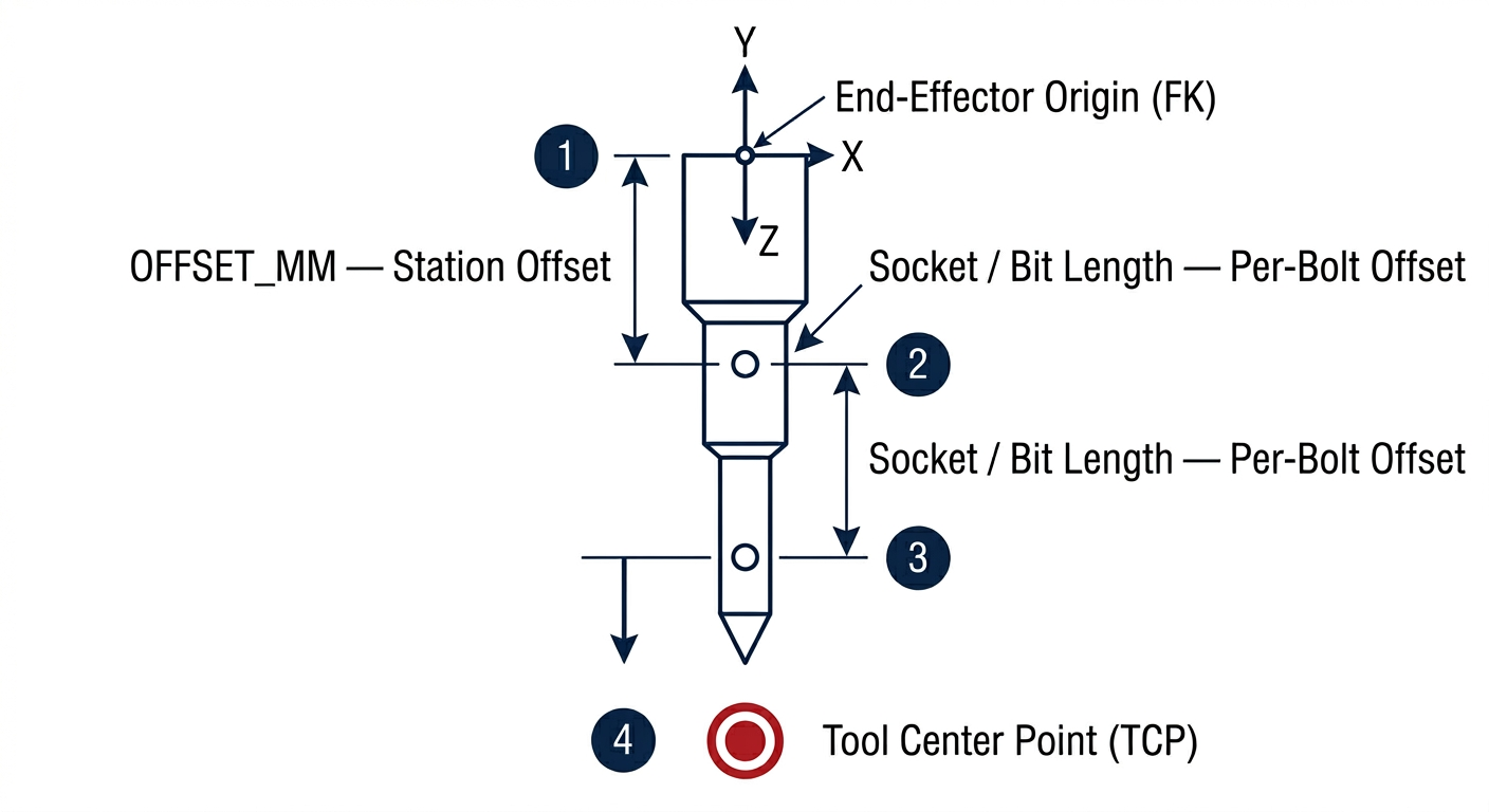
Tool-tip offset
The tool-tip position is computed by projecting a distance along the tool's Z-axis from the end-effector origin. The total offset is the sum of:
- Station offset (
OFFSET_MMinstation.ini) — compensates for fixed adapters or quick-change couplings mounted on the tool - Per-bolt offset — set in the tolerance parameters during teach-in (socket/bit length)
This matches the same offset concept used by the ART driver — the difference is that the ROBOT driver computes the tool center point via FK instead of receiving it from an optical tracker.
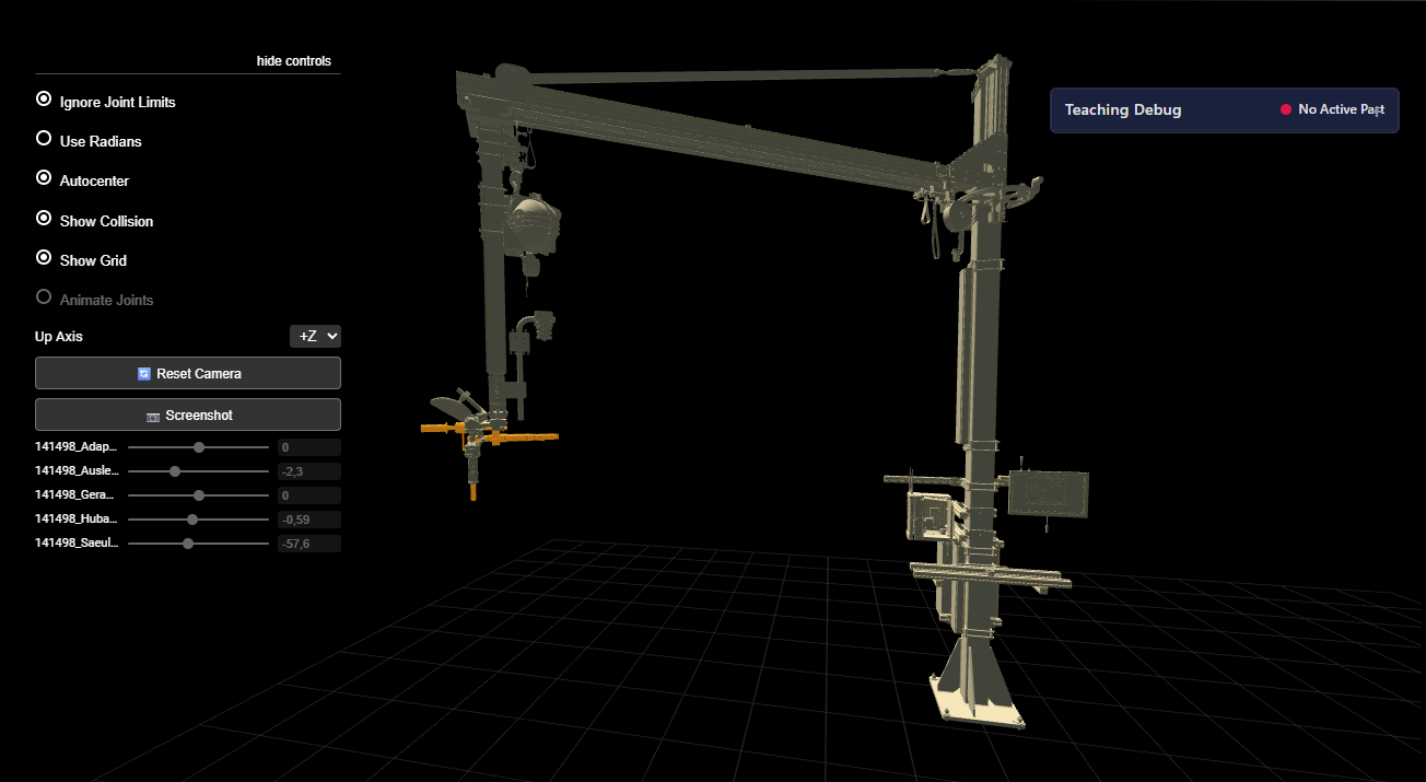
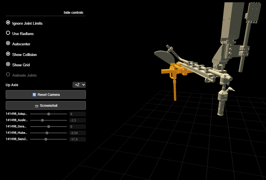
URDF 3D viewer
The OGS start page can display an interactive 3D visualization of the URDF robot model in the browser. The viewer renders the robot meshes and shows joint positions updating in real-time as sensor values change.
To enable the viewer, include startpage_urdf in config.lua and set the billboard:
requires = {
    "lib.positioning",
    "startpage_urdf",           -- 3D URDF robot viewer
    "station_io",
    -- ...
}
current_project.billboard = 'startpage_urdf.html'
The viewer reads KINEMATIC_FILE from the positioning section in station.ini and loads the corresponding URDF model and mesh files. The initial camera view can be configured in the same section (see camera configuration).
Initial system setup
Prerequisites
- OGS V3.1.10 or later
- Network access to the IO-Link master(s) connected to the joint sensors
- A URDF robot model describing the handling system's kinematics (generated from CAD)
- IO-Link sensors mounted on each movable joint
Project folder structure
MyProject/
├── ST-MyStation/
│   ├── config.lua           # Module loading
│   ├── station.ini          # Hardware and positioning configuration
│   ├── station_io.lua       # Station I/O (uses station_io_robot_enip)
│   ├── custom.lua           # Station-specific code (optional)
│   └── model/
│       ├── my_robot.urdf    # URDF kinematic model
│       └── meshes/          # STL mesh files for visualization
│           ├── base_link.stl
│           ├── arm_link.stl
│           └── ...
OGS configuration
config.lua
As described in OGS positioning overview, include lib.positioning in your config.lua. The ROBOT driver additionally needs the station I/O module for reading sensors, and optionally the URDF viewer:
OGS.Project.AddPath('../shared')

requires = {
    "lib.positioning",              -- (1)!
    "startpage_urdf",               -- (2)!
    "station_io",                   -- (3)!
    "custom",
}
current_project.billboard = 'startpage_urdf.html'
- Core positioning — automatically loads the ROBOT driver based on
DRIVER=ROBOTinstation.ini - Optional: browser-based 3D URDF robot viewer on the start page
- Station I/O — reads sensor data via Ethernet/IP and maps to FK joints
station.ini — Driver parameters
As described in OGS positioning overview, link a tool channel to the positioning section. Then configure the ROBOT-specific parameters:
[OPENPROTO]
CHANNEL_01=10.10.2.164
CHANNEL_01_TYPE=Nexo
CHANNEL_01_PORT=4545
; --> Enable positioning for this channel
CHANNEL_01_POSITIONING=POSITIONING_ENIP_CH1
; IMPORTANT: cyclic external condition checking must be enabled
CHANNEL_01_CHECK_EXT_COND=1

[POSITIONING_ENIP_CH1]
; Use the ROBOT (forward kinematics) positioning driver
DRIVER=ROBOT
; Grace period (ms) before disabling tool after leaving position (default: 0)
TIMEOUT=1000
; Station-level tool-tip offset in mm (adapter/quick-change length, NOT socket)
OFFSET_MM=0
; Path to URDF kinematic model (relative to project folder)
KINEMATIC_FILE=model/my_robot.urdf
; End-effector link name in the URDF. If omitted, auto-detected as the
; terminal link of the kinematic chain.
KINEMATIC_END_EFFECTOR=my_tool_link
; Debug trace level (0=off, ≥1=log TCP position, ≥2=verbose FK)
DEBUG=0
Parameter reference:
| Parameter | Required | Default | Description |
|---|---|---|---|
DRIVER |
Yes | — | Must be ROBOT |
TIMEOUT |
No | 0 |
Grace period (ms) before disabling tool after leaving position. Set to -1 for one-shot enable. |
OFFSET_MM |
No | 0 |
Station-level tool-tip offset in mm. Added to per-bolt offset from teach-in. Use for fixed adapters. |
KINEMATIC_FILE |
Yes | — | Relative path to the URDF file |
KINEMATIC_END_EFFECTOR |
No | (auto) | End-effector link name. If omitted, the terminal link in the chain is used. |
DEBUG |
No | 0 |
XTRACE debug level. 0=off, ≥1=log offsets and TCP, ≥2=verbose FK. |
Camera configuration
Optional parameters in the same positioning section control the initial view of the 3D URDF viewer:
; Camera position (XYZ in meters, in URDF base-frame coordinates)
CAMERA_POSITION_X=1.11
CAMERA_POSITION_Y=2.42
CAMERA_POSITION_Z=2.25
; Camera look-at target (XYZ in meters)
CAMERA_TARGET_X=0.96
CAMERA_TARGET_Y=2.40
CAMERA_TARGET_Z=1.86
; Zoom level (1 = default)
CAMERA_ZOOM=1
You can adjust the camera interactively in the 3D viewer and then copy the values back to station.ini.
Joint-to-sensor mapping
Each movable URDF joint that has a physical sensor requires a mapping section. The section name follows the pattern [<POSITIONING_SECTION>:<URDF_JOINT_NAME>]:
; Rotary encoder on IO-Link port 1
[POSITIONING_ENIP_CH1:base_rotation]
DEVICE=IOLINK_MASTER
PORT=1

; Distance sensor on port 2, inverted direction
[POSITIONING_ENIP_CH1:arm_extension]
DEVICE=IOLINK_MASTER
PORT=2
SCALE=-1
OFFSET=0
| Parameter | Required | Default | Description |
|---|---|---|---|
DEVICE |
Yes | — | Logical name of the IO-Link master (as defined in [STATION_IO_ENIP]) |
PORT |
Yes | — | IO-Link port number (1–8) on the master |
SCALE |
No | 1.0 |
Multiplier applied to the decoded sensor value. Use -1 to invert direction if sensor mounting is reversed. |
OFFSET |
No | 0.0 |
Value added after scaling (radians for rotary, meters for linear sensors) |
Note
Only joints with a physical sensor need a mapping section. URDF fixed joints are automatically skipped. If a movable joint has no mapping, a warning is logged but the system continues — that joint will stay at its URDF default value (clamped to joint limits).
Ethernet/IP and IO-Link setup
IO-Link master
Define Ethernet/IP devices in the [STATION_IO_ENIP] section:
[STATION_IO_ENIP]
; Format: <logical_name>=<ip_address>,<device_model>
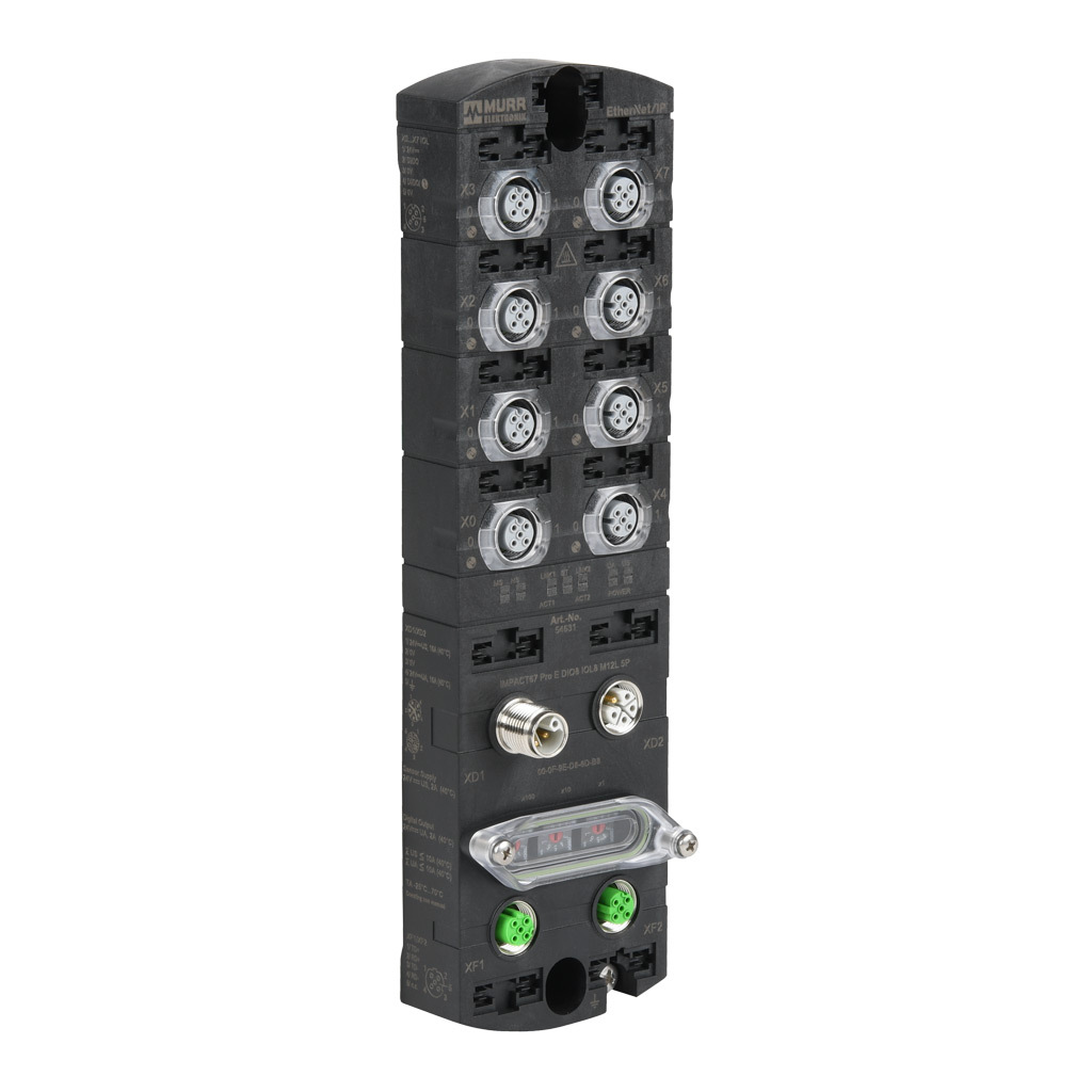
IOLINK_MASTER=192.168.100.150,MURR_IMPACT67_PROE
; Debug level: 0=off, 1=errors, 2=warnings, 3=verbose
DEBUG=0
Supported IO-Link masters:
| Model | Manufacturer | Ports | Notes |
|---|---|---|---|
MURR_IMPACT67_PROE |
Murrelektronik | 8 | Impact67 Pro-E, 40 bytes per port |
BalluffBNI006A |
Balluff | 8 | BNI006A, full EDS connection |
IO-Link port assignments
Map ports to sensor models in a section named after the logical master name:
[IOLINK_MASTER]
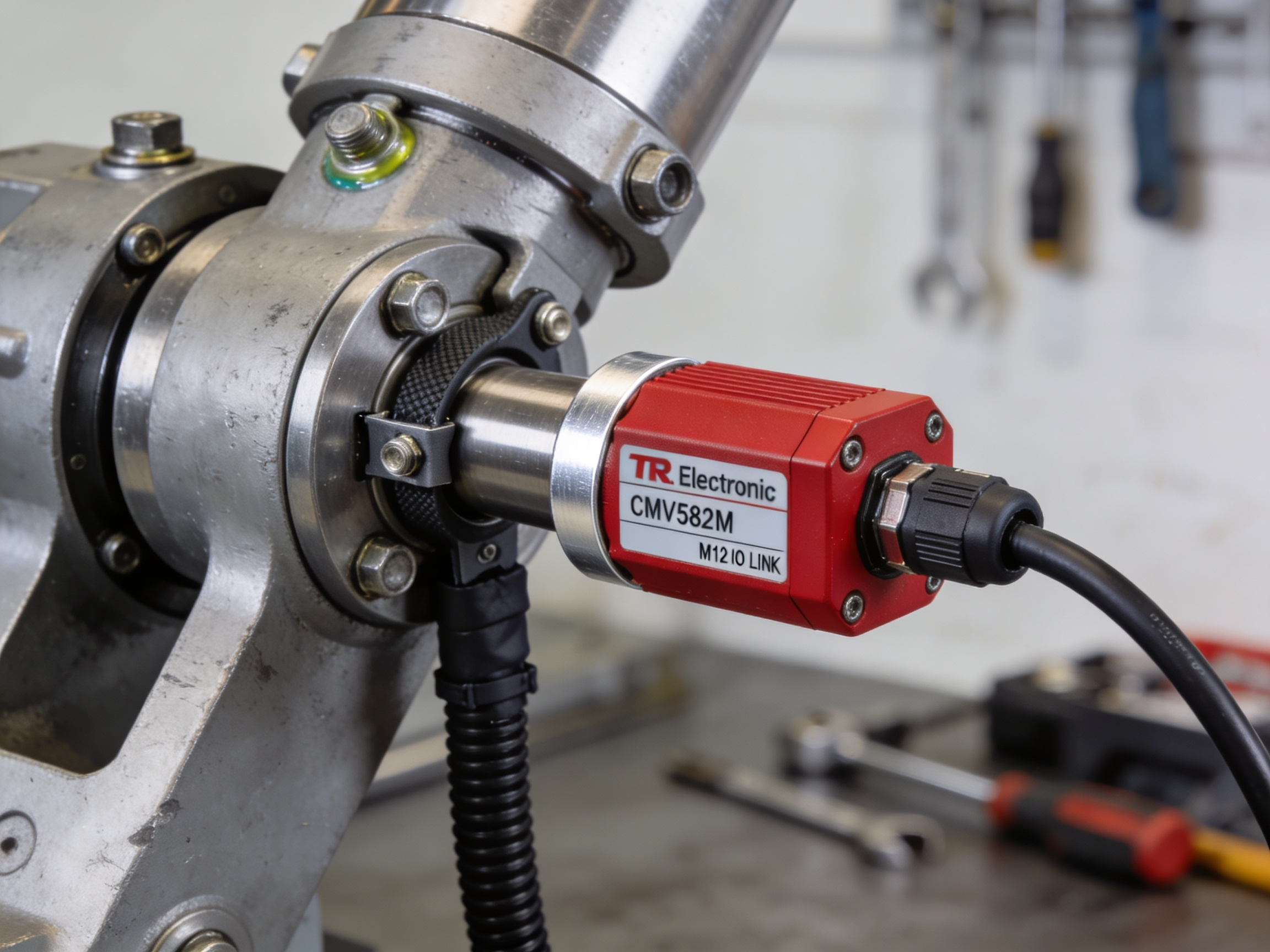
PORT1=TR_CMV582M-00028 ; Rotary encoder
PORT2=Wenglor_P1PY101 ; Linear distance sensor
PORT3=TR_CMV582M-00028
PORT4=Wenglor_P1PY101
; Ports 5-8 unused
Supported sensors
TR Electronic CMV582M — Rotary encoder
| Property | Value |
|---|---|
| Model | TR_CMV582M-00028 |
| Type | Absolute rotary encoder (IO-Link) |
| Output unit | Radians |
| Resolution | 4096 increments/revolution |
| Conversion | $\theta = 2\pi \times \frac{\text{increments}}{4096}$ |
Supports writing a preset value for homing/referencing.
Wenglor P1PY101 — Laser distance sensor
| Property | Value |
|---|---|
| Model | Wenglor_P1PY101 |
| Type | Laser distance sensor (IO-Link) |
| Output unit | Meters |
| Conversion | $d = \frac{\text{raw}}{1000}$ (raw is in mm) |
Special status values (returned as sensor error, no numeric value):
| Raw value | Meaning |
|---|---|
0x7FF8 |
Object too far |
0x8008 (signed) |
Object too near |
0x7FFC |
No signal |
Adding new sensor types
New IO-Link sensor types can be added by defining their decode/encode functions in iolink_devices.lua. Each entry provides fnDecodeInput(raw) returning the engineering-unit value and an optional status string.
URDF model preparation
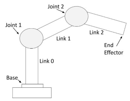
The URDF file defines the kinematic chain of the handling system. It uses standard ROS URDF format.
Requirements:
- Joint types:
revolute,prismatic, andfixedare supported. Fixed joints define static geometry and require no sensor. - Units: Positions in meters, angles in radians (standard URDF convention).
- Mesh files: STL format, referenced as
<mesh filename="meshes/link_name.stl" scale="0.001 0.001 0.001" />. Thescaleconverts from CAD units (typically mm) to meters. - Joint limits: Define
<limit lower="..." upper="..." />for all movable joints. The FK solver clamps initial joint values to these limits.
Joint default clamping
A prismatic joint with lower="0.5" will not start at zero — the FK solver clamps the initial default into [lower, upper]. This is intentional to prevent physically impossible starting positions.
Example URDF fragment
<robot name="my_arm">
    <link name="base_link">
        <visual>
            <geometry>
                <mesh filename="meshes/base_link.stl" scale="0.001 0.001 0.001" />
            </geometry>
        </visual>
    </link>

    <joint name="base_rotation" type="revolute">
        <parent link="base_link" />
        <child link="arm_link" />
        <origin xyz="0 0 1.5" rpy="0 0 0" />
        <axis xyz="0 0 1" />
        <limit lower="-3.14" upper="3.14" />
    </joint>

    <link name="arm_link">
        <visual>
            <geometry>
                <mesh filename="meshes/arm_link.stl" scale="0.001 0.001 0.001" />
            </geometry>
        </visual>
    </link>

    <!-- Fixed joint to tool (no sensor needed) -->
    <joint name="tool_mount" type="fixed">
        <parent link="arm_link" />
        <child link="tool_link" />
        <origin xyz="0 0 -0.3" rpy="0 0 0" />
    </joint>

    <link name="tool_link" />
</robot>
File placement
Place the URDF and mesh files in the station's model/ directory:
ST-MyStation/
└── model/
    ├── my_robot.urdf
    └── meshes/
        ├── base_link.stl
        ├── arm_link.stl
        └── tool_link.stl
The web server maps the /model URL to this directory automatically, so the 3D viewer can load the mesh files.
Generating URDF from CAD
URDF files are typically exported from CAD assemblies. The STL meshes should be placed in a meshes/ subfolder. URDF <mesh> references use paths relative to the URDF file location.
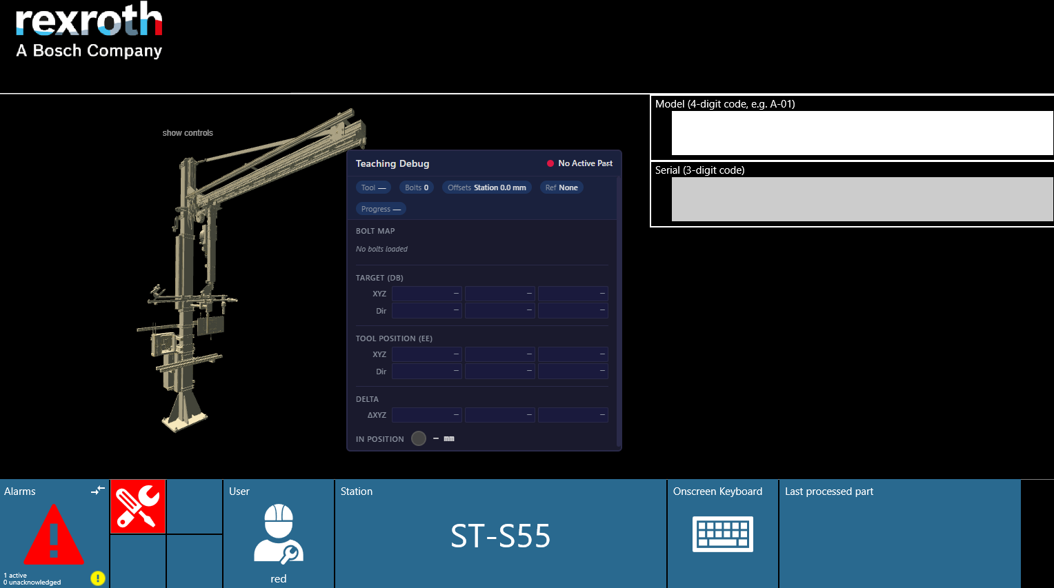
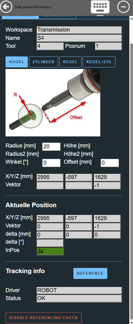
Sidepanel teach-in setup
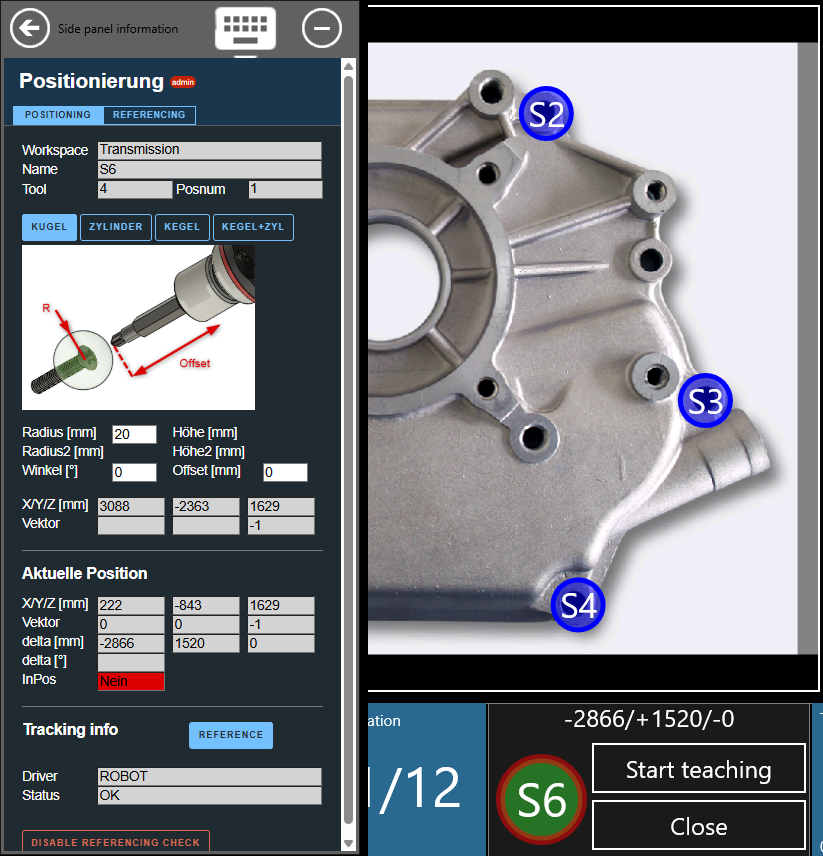
The webserver configuration for the side panel is identical to the general OGS positioning setup — see OGS positioning overview and ART sidepanel setup for the [WebServer] and [SidePanel] configuration.
The sidepanel shows ROBOT in the "Tracking info" section (section ❹) instead of ART. All other functionality (tolerance body selection, offset, teach position) works identically:
- ❶ Job, task and position information
- ❷ Tolerance parameters and taught coordinates
- ❸ Current position and difference values
- ❹ Tracking info showing
ROBOTdriver status
Complete configuration example
A full working station.ini for a station with a Nexo tool and a 4-joint handling arm (2 rotary encoders + 2 linear sensors):
[OPENPROTO]
CHANNEL_01=10.10.2.164
CHANNEL_01_TYPE=Nexo
CHANNEL_01_PORT=4545
CHANNEL_01_CHECK_TIME_ENABLED=1
CHANNEL_01_CCW_ACK=1
CHANNEL_01_POSITIONING=POSITIONING_ENIP_CH1
CHANNEL_01_CHECK_EXT_COND=1

[POSITIONING_ENIP_CH1]
DRIVER=ROBOT
TIMEOUT=1000
OFFSET_MM=0
KINEMATIC_FILE=model/141497_C91_heat_exchanger.urdf
KINEMATIC_END_EFFECTOR=141497_Schraubwerkzeug-v1

CAMERA_POSITION_X=1.11
CAMERA_POSITION_Y=2.42
CAMERA_POSITION_Z=2.25
CAMERA_TARGET_X=0.96
CAMERA_TARGET_Y=2.40
CAMERA_TARGET_Z=1.86
CAMERA_ZOOM=1

; Joint-to-sensor mapping (section name = POSITIONING_SECTION:URDF_JOINT_NAME)
[POSITIONING_ENIP_CH1:141497_Saeule-v1_Schwenken-Ausleger]
DEVICE=IOLINK_MASTER
PORT=1

[POSITIONING_ENIP_CH1:141497_Schwenkarm-v1_Y-Hub-Ausleger]
DEVICE=IOLINK_MASTER
PORT=2
SCALE=-1

[POSITIONING_ENIP_CH1:141497_Hubachse-v1_schwenken_Adaption]
DEVICE=IOLINK_MASTER
PORT=3
SCALE=-1

[POSITIONING_ENIP_CH1:141497_hl-v1_Z-Hub-Geraet]
DEVICE=IOLINK_MASTER
PORT=4

; Ethernet/IP fieldbus
[STATION_IO_ENIP]
IOLINK_MASTER=192.168.100.150,MURR_IMPACT67_PROE
DEBUG=0

[IOLINK_MASTER]
PORT1=TR_CMV582M-00028
PORT2=Wenglor_P1PY101
PORT3=TR_CMV582M-00028
PORT4=Wenglor_P1PY101

; Webserver (required for sidepanel and URDF viewer)
[WebServer]
URL=http://127.0.0.1:60000/
RootFolder=../shared/webroot

[SidePanel]
URL=local://sidepanel.html
Key=112
Width=24
Troubleshooting
Sensor issues
| Symptom | Cause | Solution |
|---|---|---|
| "No position info available" | IO-Link master not connected | Check Ethernet cable and IP in [STATION_IO_ENIP] |
| Joint stuck at default value | Missing joint mapping section | Add [POSITIONING_SECTION:joint_name] to station.ini |
| Position jumps or oscillates | Incorrect SCALE |
Verify sensor mounting direction; use SCALE=-1 to invert |
| Constant position offset | Wrong OFFSET value |
Measure at a known reference point and adjust OFFSET |
| Sensor returns no data | Object out of range (Wenglor) | Check that workpiece is within sensor measurement range |
URDF / FK issues
| Symptom | Cause | Solution |
|---|---|---|
| "Error loading URDF file" | File not found or invalid XML | Verify KINEMATIC_FILE path is relative to the project folder |
| "Could not determine end-effector" | No terminal link in URDF | Set KINEMATIC_END_EFFECTOR explicitly |
| Position scaled incorrectly | Wrong mesh scale in URDF |
Ensure scale="0.001 0.001 0.001" if CAD is in mm |
| Joint starts at unexpected value | Default clamped to URDF limits | Expected for joints where lower > 0 |
Configuration errors
| Symptom | Cause | Solution |
|---|---|---|
| "Positioning without cyclic enable check" | CHECK_EXT_COND not set |
Add CHANNEL_xx_CHECK_EXT_COND=1 to [OPENPROTO] |
| "unknown/missing DRIVER" | Typo in DRIVER= value |
Must be exactly ROBOT |
| "No IO-Link joints mapped" | No sensor sections defined | Add at least one [POSITIONING_SECTION:joint_name] section |