Part Referencing
Version
Part referencing is available starting with OGS V3.1.10 or later.
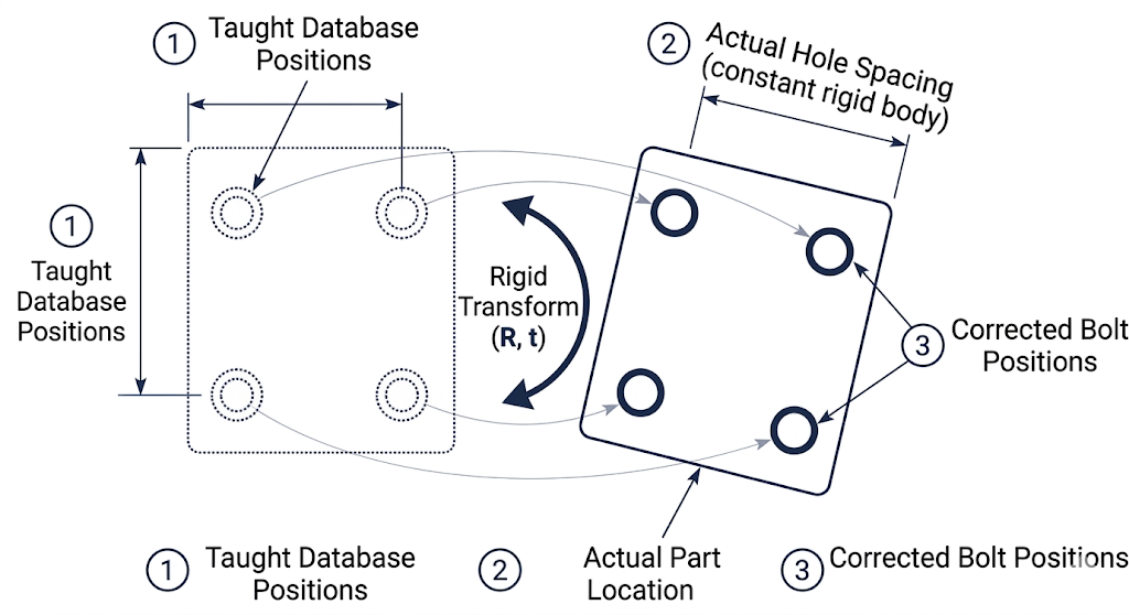
Part referencing compensates for variation in how a workpiece is placed in the station. When a new part arrives, it may be shifted or rotated compared to the position where bolt positions were originally taught. Referencing captures known positions on the actual part and computes a rigid-body transform to map the taught (database) coordinates to the actual part position, so that all subsequent positioning checks use corrected coordinates automatically.
When to use referencing
| Scenario | Referencing needed? |
|---|---|
| Part always placed in the exact same position (fixture, jig) | No — absolute coordinates work |
| Part placed by hand, position varies each cycle | Yes — reference before each part |
| Part on a conveyor with variable stop position | Yes — reference after part is positioned |
| Positions imported from CAD (part coordinates) | Yes — map from part-local to machine coordinates |
| Fixed handling system (ROBOT driver), part always at same location | No — teach directly in machine coordinates |
Referencing modes
Three referencing modes are available, configured per job via the reference_type property in the OGS workflow editor (see configuration below):
| Mode | reference_type |
Reference points | Best for |
|---|---|---|---|
| None | absent or 0 |
0 | Fixed part placement |
| Single position | 1 |
1 | Small translation offsets, known orientation |
| Two positions | 2 |
2 | Translation + rotation in one plane |
| Three positions | 3 |
3 | Full 3D translation + rotation |
Mode 2 behaviour differs by driver
Mode 2 automatically adapts its computation depending on the positioning driver:
- ROBOT driver — the direction vector is rigidly attached to the part (derived from kinematics), so OGS uses the full 6D pose (position + orientation) for a more accurate result.
- ART / optical driver — the tool axis always approaches from the same direction regardless of part orientation, so OGS uses only the 3D positions with a minimum-rotation constraint.
This is detected automatically from the DRIVER= setting in station.ini.
Prerequisites
Before referencing can work, the following conditions must be met:
- The positioning system must be configured and operational (see the OGS positioning overview and the driver-specific setup guides for ROBOT or ART)
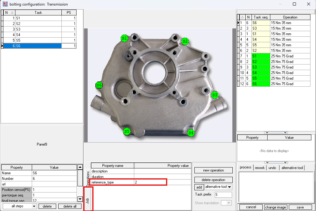
- Reference bolt tasks must have positioning enabled (PS value > 0 in the workflow editor). Only tasks with a non-zero PS value participate in position tracking — tasks with PS=0 are invisible to the referencing system. See workflow configuration for how to set the PS column.
- Reference bolt positions must be taught (recorded coordinates exist in the database)
- The
reference_typejob property must be set (see configuration below)
Info
If you can't see the PS column in the workflow editor, go to Database --> Settings and check the "Use Position Encoder" option — see the OGS positioning overview for details.
How it works
Overview
flowchart TD
    A["Job released with<br/>reference_type property"] --> B["OGS creates<br/>referencing session"]
    B --> C["Tool is enabled for<br/>reference bolt 1<br/>(distance check bypassed)"]
    C --> D["Operator tightens<br/>reference bolt 1"]
    D --> E["OGS captures<br/>tool position"]
    E --> F{"All reference<br/>points collected?"}
    F -->|No| G["Tool enabled for<br/>next reference bolt"]
    G --> D
    F -->|Yes| H["OGS computes<br/>rigid-body transform"]
    H --> I["Transform active ✓"]
    I --> J["All subsequent bolt positions<br/>automatically transformed"]
Auto-referencing flow
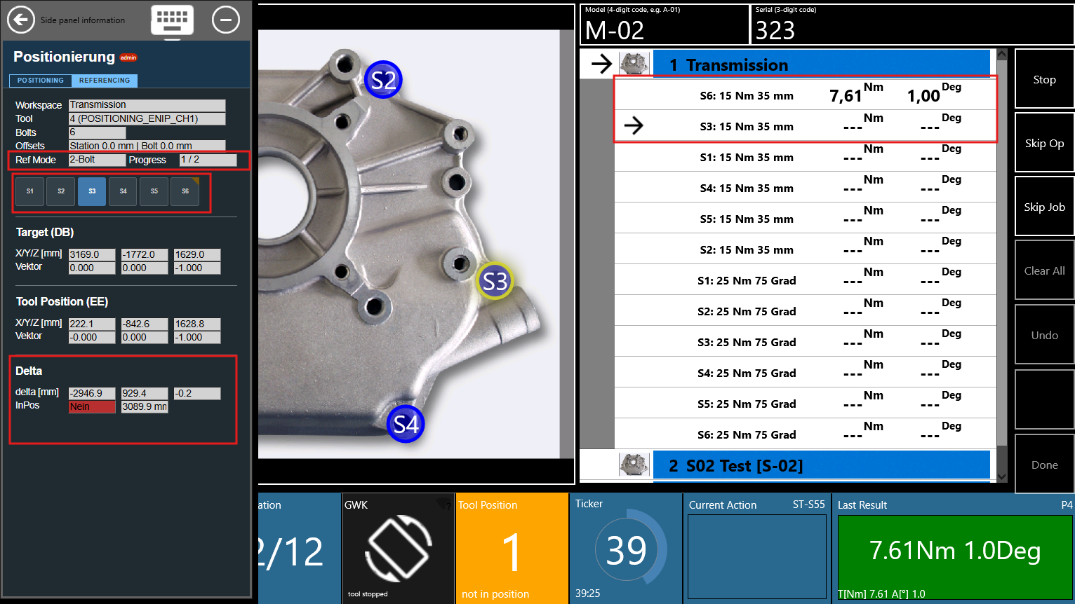
Referencing is automatic — the operator simply tightens bolts in order. OGS detects which bolt is a reference bolt and captures the position during the normal tightening cycle:
- A job with the
reference_typeproperty is released - OGS reads the property and activates referencing in the requested mode (1, 2, or 3 points)
- The first N bolts in the job's action sequence (with positioning enabled) become the reference bolt slots
- When the operator tightens reference bolt 1, OGS captures the current tool position as reference point 1
- For each subsequent reference bolt, OGS performs an inter-bolt distance plausibility check before capture (measured distance vs. database distance must match within tolerance)
- Once all N points are collected, OGS computes the rigid-body transform (rotation + translation)
- From this point on, every bolt position is automatically transformed to match the actual part placement
Reference bolts must be taught and positioning-enabled
Reference points are only captured when:
- The task has positioning enabled (PS > 0 in the workflow editor)
- The bolt position has been taught (exists in the database)
- The tightening result is OK
If any of these conditions are not met, the capture is skipped and OGS retries on the next attempt.
Position guards
During the referencing collection phase (before the transform is active), OGS enforces several position-check guards:
| Guard | Condition | Behaviour |
|---|---|---|
| Guard 0 | Supervisor bypass active | Skip ALL position checks — tool always enabled |
| Guard 1 | Current bolt is next reference slot | First bolt: distance check bypassed (no prior anchor). Subsequent bolts: inter-bolt distance plausibility check. |
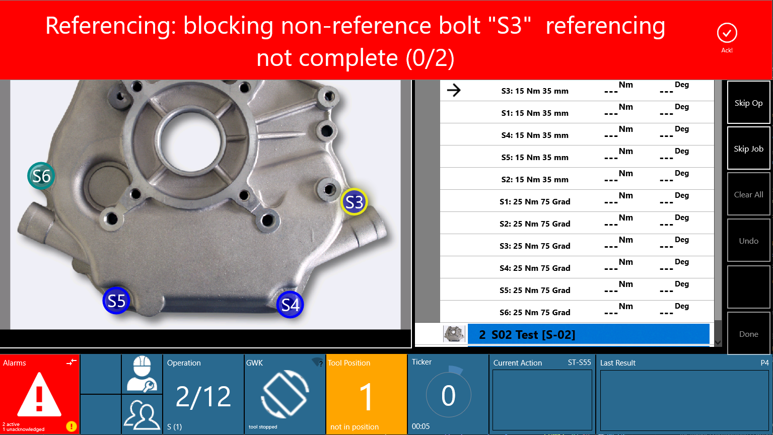
| Guard 2 | Non-reference bolt, referencing incomplete | Block tool — prevents tightening against untransformed coordinates |
| Guard 3 | Transform lost (e.g. OGS restart mid-job) | Block tool + alarm — operator must restart job or supervisor must bypass |
Supervisor bypass
A supervisor (user level ≥ 2) can bypass the referencing check via the sidepanel. When bypass is active:
- All position checks are skipped (tool is always enabled)
- A status message "Supervisor bypass active — referencing check disabled for this job." is shown
- The bypass persists across workflow pause/resume within the same part
- The bypass is cleared when a new part is scanned
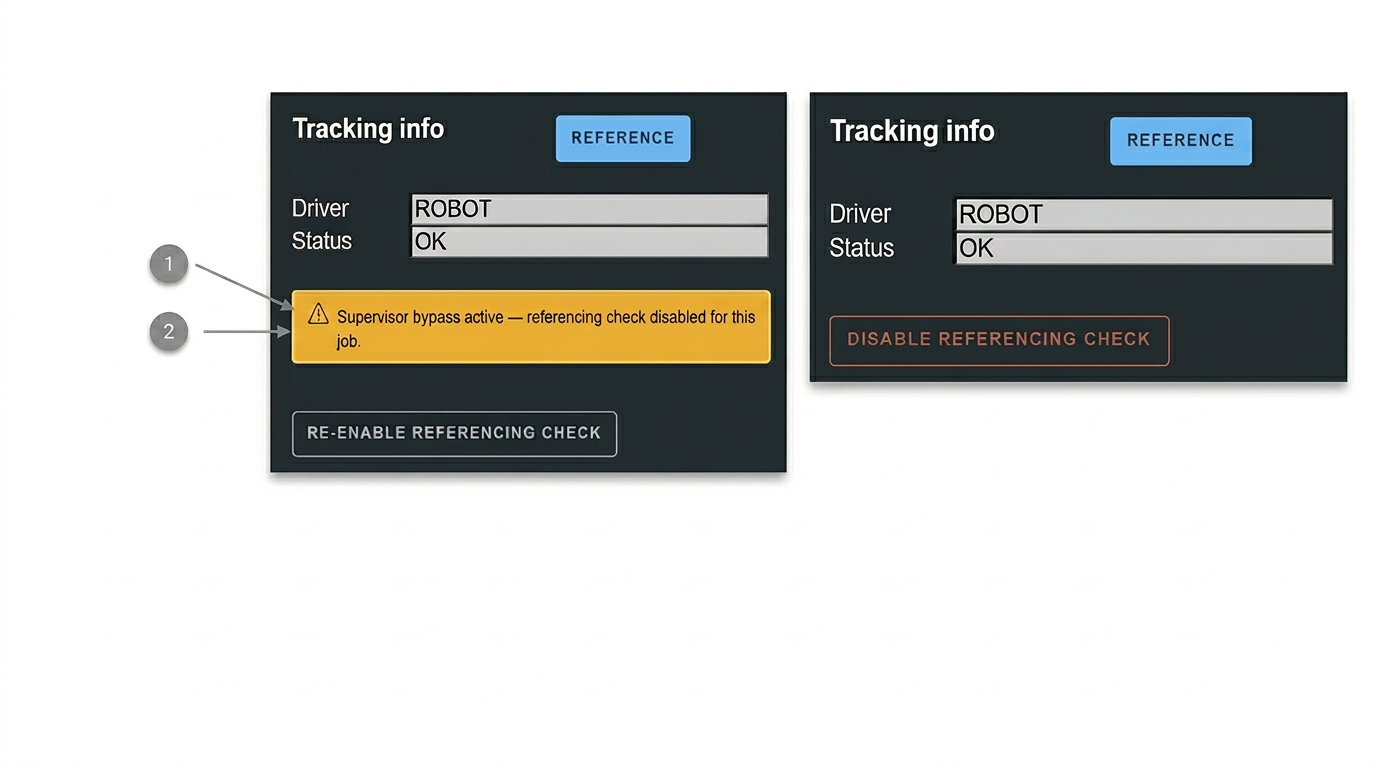
Important
Use the supervisor bypass only as a last resort (e.g. after OGS restart mid-job). When bypass is active, bolt positions are not checked against the referencing transform, so the operator must ensure the correct position manually.
Restart detection
If OGS is restarted while a referenced job is in progress, the in-memory transform is lost. OGS detects this by checking whether reference bolt tasks are already marked as tightened in the workflow state:
- If tightened reference bolts are found but no transform exists, OGS sets an alarm and blocks all bolts
- The operator must either restart the job from the beginning or ask a supervisor to bypass referencing
Error classification
When the solver fails, errors are classified into two categories:
| Category | Description | Action |
|---|---|---|
| CONFIG | Bolt layout unsuitable (collinear bolts, identical positions) | Always fails — change the reference bolt configuration |
| MEASUREMENT | Transient failure (measurement noise, distance mismatch) | May succeed on retry — retighten the reference bolt |
CONFIG errors trigger a persistent alarm with guidance text. MEASUREMENT errors allow the operator to retry the bolt (OGS rejects the tightening result and prompts for a retry).
Configuration
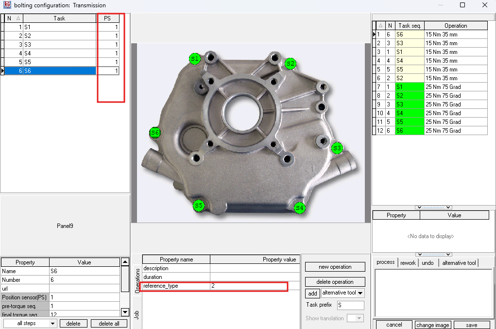
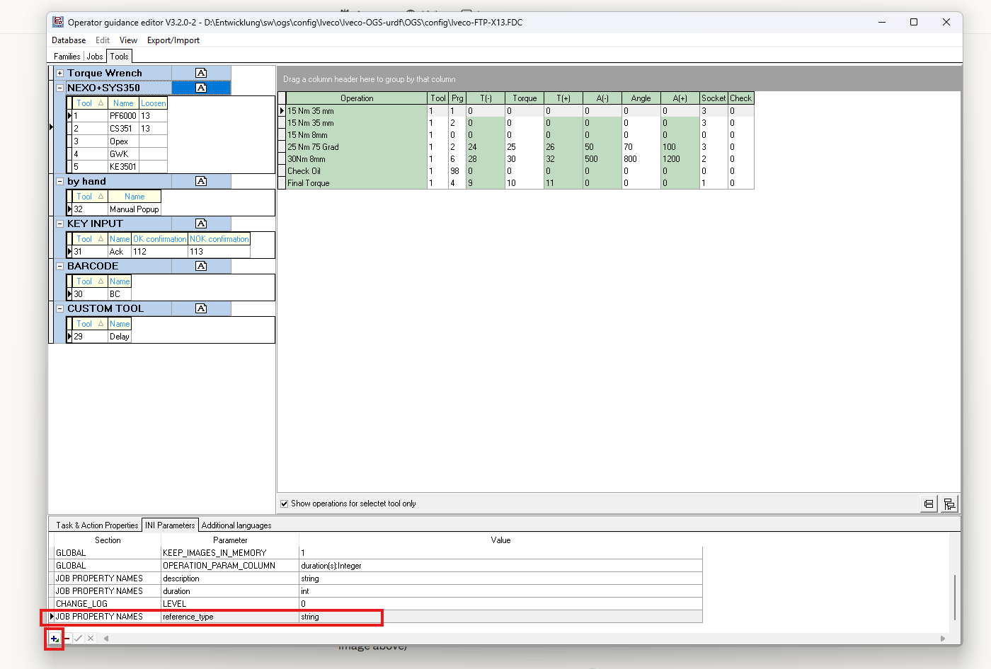
Setting reference_type in the workflow editor
The referencing mode is configured as a job property in the OGS workflow configurator (heOpCfg):
- Open the workflow editor (heOpCfg)
- Select the job that requires referencing
- In the INI Parameters tab, locate the JOB PROPERTY NAMES section
- Add a new property with the name
reference_typeand typestring - Set the value to
1,2, or3depending on the desired referencing mode
The property value can also be set in the operations properties panel at the bottom of the heOpCfg editor for a specific job.
| Property | Value | Effect |
|---|---|---|
reference_type |
absent or empty | Referencing disabled for this job |
reference_type |
1 |
Single-position 6D referencing |
reference_type |
2 |
Two-position referencing |
reference_type |
3 |
Three-position referencing |
Per-job configuration
Each job can have a different reference_type value. This allows mixing referenced and non-referenced jobs within the same part/workflow. The referencing state is initialised fresh each time a job is released.
Which bolts become reference points?
OGS automatically selects the reference bolts from the job's action sequence:
- Actions are sorted by their sequence number (ascending)
- Only actions whose tool is assigned to a positioning channel and whose task has positioning enabled (PS > 0) are considered
- The first N such actions become the reference bolt slots (where N =
reference_type)
The reference bolt names are taken from the corresponding task names in the workflow.
Note
All reference measurements use the same tool — the tool from the first positioning action is locked for the entire referencing session. This means the same tightening tool must be used for all reference bolts, even if other tools are configured for subsequent production bolts.
station.ini parameters
No additional station.ini parameters are required for referencing — it is driven entirely by the reference_type job property. The referencing engine uses the existing positioning driver configuration (DRIVER=ROBOT or DRIVER=ART).
Plausibility thresholds
When adding subsequent reference points (2nd, 3rd), OGS checks whether the measured inter-bolt distance matches the database distance. The threshold is computed as follows:
threshold = max( 2 × max(r1_prev, r1_current) , 50 mm )
Where:
- r1_prev is the taught tolerance radius of the previously collected reference bolt
- r1_current is the taught tolerance radius of the current bolt being added
- The minimum threshold is always 50 mm
For example, if both reference bolts have a tolerance radius of 20 mm, the threshold is max(2 × 20, 50) = 50 mm. If a bolt has radius 40 mm, it becomes max(2 × 40, 50) = 80 mm.
If the distance error exceeds this threshold, the reference point is rejected and the operator must retry.
Referencing modes in detail
Single position (mode 1)
Input: One 6D reference point (position + orientation).
What OGS computes: The rigid-body transform from a single taught/measured pose pair.
Best for: Parts that are always placed in a similar orientation but shifted in position. Requires only one reference bolt tightening.
Limitation: Assumes the part's Z-plane is approximately parallel to the machine Z-plane. If the part is also rotated, use mode 2 or 3.
Two positions (mode 2)
Input: Two 3D reference points (with optional orientation for the ROBOT driver).
ROBOT driver: Uses the full 6D pose at each reference point. The direction vector from the kinematic chain is rigidly attached to the part, giving the computation additional orientation information.
ART / optical driver: Uses only the 3D positions with a minimum-rotation constraint. The tool axis direction is not part-fixed for optical trackers.
Best for: Parts that can shift and rotate in one plane (typical for horizontal assembly). Two reference bolts provide enough constraints for 2D rotation + 3D translation.
Limitation: The rotation around the line connecting the two reference points is underdetermined. Choose reference bolts that are well separated — collinear or nearly overlapping bolts will cause a CONFIG error.
Three positions (mode 3)
Input: Three 3D reference points.
What OGS computes: The full 3D rigid-body transform from three point pairs.
Best for: Parts with full 3D orientation variation. Three non-collinear bolts fully define the rigid body transform.
Limitation: The three reference bolts must form a triangle (not a straight line). Collinear bolts will cause a CONFIG error.
Typical operator workflow
Normal operation (no issues)
Here is a typical 2-point referencing workflow:
sequenceDiagram
    participant Op as Operator
    participant OGS as OGS Runtime

    Op->>OGS: Scan part barcode
    OGS->>OGS: Load part, release job (reference_type=2)
    OGS->>Op: Guide to reference bolt S1
    Note over OGS: Distance check bypassed for bolt 1
    Op->>OGS: Tighten S1 (OK)
    OGS->>OGS: Capture position → reference point 1
    OGS->>Op: Guide to reference bolt S2
    Note over OGS: Inter-bolt distance plausibility check
    Op->>OGS: Tighten S2 (OK)
    OGS->>OGS: Capture position → reference point 2
    OGS->>OGS: Compute rigid-body transform ✓
    OGS->>Op: Guide to production bolts
    Note over OGS: All positions now use transformed coordinates
Step by step:
- Scan the part barcode → OGS loads the part
- First job is released → OGS reads
reference_type=2→ referencing session starts - OGS guides operator to reference bolt S1 → tool is enabled (distance check bypassed)
- Operator tightens S1 → position captured as reference point 1
- OGS guides operator to reference bolt S2 → tool is enabled (inter-bolt distance check)
- Operator tightens S2 → position captured as reference point 2 → transform computed and active
- OGS guides operator through remaining production bolts → all positions use transformed coordinates
- Repeat for subsequent jobs (each may have its own
reference_type)
Handling errors
Tightening result NOK on a reference bolt:
- OGS keeps the referencing state unchanged
- The bolt is retried (standard NOK handling)
- Once the bolt tightening is OK, the reference point is captured
Distance mismatch on reference bolt 2 or 3:
- The reference point is rejected, alarm is shown
- The operator must retighten the bolt (move tool to the correct position)
- The rejection does not affect previously collected reference points
OGS restart mid-referenced-job:
- OGS detects that reference bolts are already tightened but no transform exists
- An alarm is shown: "Referencing data lost during restart!"
- Operator must restart the job from the beginning, or supervisor must bypass
Non-reference bolt blocked (Guard 2):
- If the operator navigates to a production bolt before referencing is complete, OGS blocks the tool
- A blocking alarm banner is shown, e.g.: "Referencing: blocking non-reference bolt 'S3' referencing not complete (0/2)"
- The operator must complete the reference bolt tightening first, or use supervisor bypass
Side panel integration
The positioning sidepanel shows referencing state information when referencing is active:
- ❶ Referencing state: Shows the current mode and progress (e.g. "Ref Mode: 2-Bolt, Progress: ½")
- ❷ Bypass toggle: Supervisors (level ≥ 2) can enable/disable the referencing bypass
Troubleshooting
Reference bolt issues
| Symptom | Cause | Solution |
|---|---|---|
| Reference point not captured | Bolt position not taught in DB | Teach the reference bolt position first |
| Reference point not captured | Tightening result was NOK | Retry the bolt — capture only happens on OK results |
| "Distance mismatch" on bolt ⅔ | Tool position too far from expected | Verify the tool is at the correct bolt; check sensor accuracy |
| "Reference bolts are collinear" | All reference bolts on a straight line | Choose bolts that form a triangle |
| "Two reference bolt positions are identical" | Same bolt taught at same position | Use distinct bolt locations for reference points |
Workflow issues
| Symptom | Cause | Solution |
|---|---|---|
| Referencing not activating | reference_type property missing on job |
Add property in heOpCfg (see configuration) |
| Non-reference bolts blocked | Referencing incomplete | Complete the reference bolt tightening first, or use supervisor bypass |
| "Referencing data lost" alarm | OGS restarted mid-referenced-job | Restart the job from the beginning, or supervisor bypass |
| Transform not applying | reference_type = 0 or absent |
Set reference_type to 1, 2, or 3 on the job |
| Wrong reference bolts selected | Action sequence order unexpected | Check the action sequence in heOpCfg — first N positioning actions become reference slots |
Configuration errors
| Symptom | Cause | Solution |
|---|---|---|
| CONFIG error: "collinear" | Bolt geometry unsuitable | Choose reference bolts forming a triangle |
| CONFIG error: "degenerate" | Positions too close or identical | Use bolts at distinct, well-separated locations |
| MEASUREMENT error: "determinant" | Measurement noise distorted the result | Retry — check tracking/sensor accuracy |